
HP Virtual Connect Domain Setup - Part 2: Network Setup
In the first postof the series I introduced to you HP Virtual Connect and showed how to use the Domain Wizard Setup to initially configure a VC domain. In the following article I will outline the use of the Network Setup Wizard and explain Virtual Connect networking concepts.
Before we begin to setup the network it would be very useful to clarify the Virtual Connect port terminology.
- External port - The Ethernet connectors SFP+ modules (either 1GB or 10GB), 10GBASE-CX4 and RJ-45 on the faceplate of the Ethernet module.
- Stacking port - These are Ethernet external ports used to connect within a Virtual Connect Domain the VC Ethernet modules. The Ethernet modules automatically identify the stacking modules.
- Uplink port - An external port configured within a Domain for use as a connection to the external networking equipment. These ports are defined within Virtual Connect by the enclosure name, interconnect bay that contains the module and the port number.
- Uplink port set - A set of uplinks ports trunked together in order to provide improved throughput and availability.
- Shared uplink port - This is an Ethernet uplink port that carries the traffic for multiple networks. The associated networks are mapped to a specific VLAN on the external connection, the appropriate VLAN tags are removed or added as Ethernet packets enter or leave the VC Domain.
- Shared uplink port set - This is a group of Ethernet uplinks trunked to provide improved throughput and availability to VC Shared Uplink Set.
The Virtual Connect Network Setup Wizard will help to establish external Ethernet connectivity for the enclosure. With this wizard you will be able to:
- Identify the MAC addresses to be used by the servers within the VC Domain.
- Configure Server VLAN tagging.
- Set up connections from the c-Class enclosure to the external networks.
The network connections can be:
- Dedicated uplink to a specific Ethernet network.
- Shared uplink sets.
The first screen of the wizard is the MAC Address Settings. As every server in the market the HP Blades come with factory-default MAC addresses already assigned to their network cards. However Virtual Connect can override these values while the server remains in the enclosure.
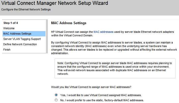
Virtual Connect access the NICs through the Onboard Administrator and the server iLO to manage the MAC addresses. It provides 64 predefined and reserved MAC address ranges. The wizard will give you the option to use either an HP predefined range or an user defined one. HP recommends to use the predefined ranges.
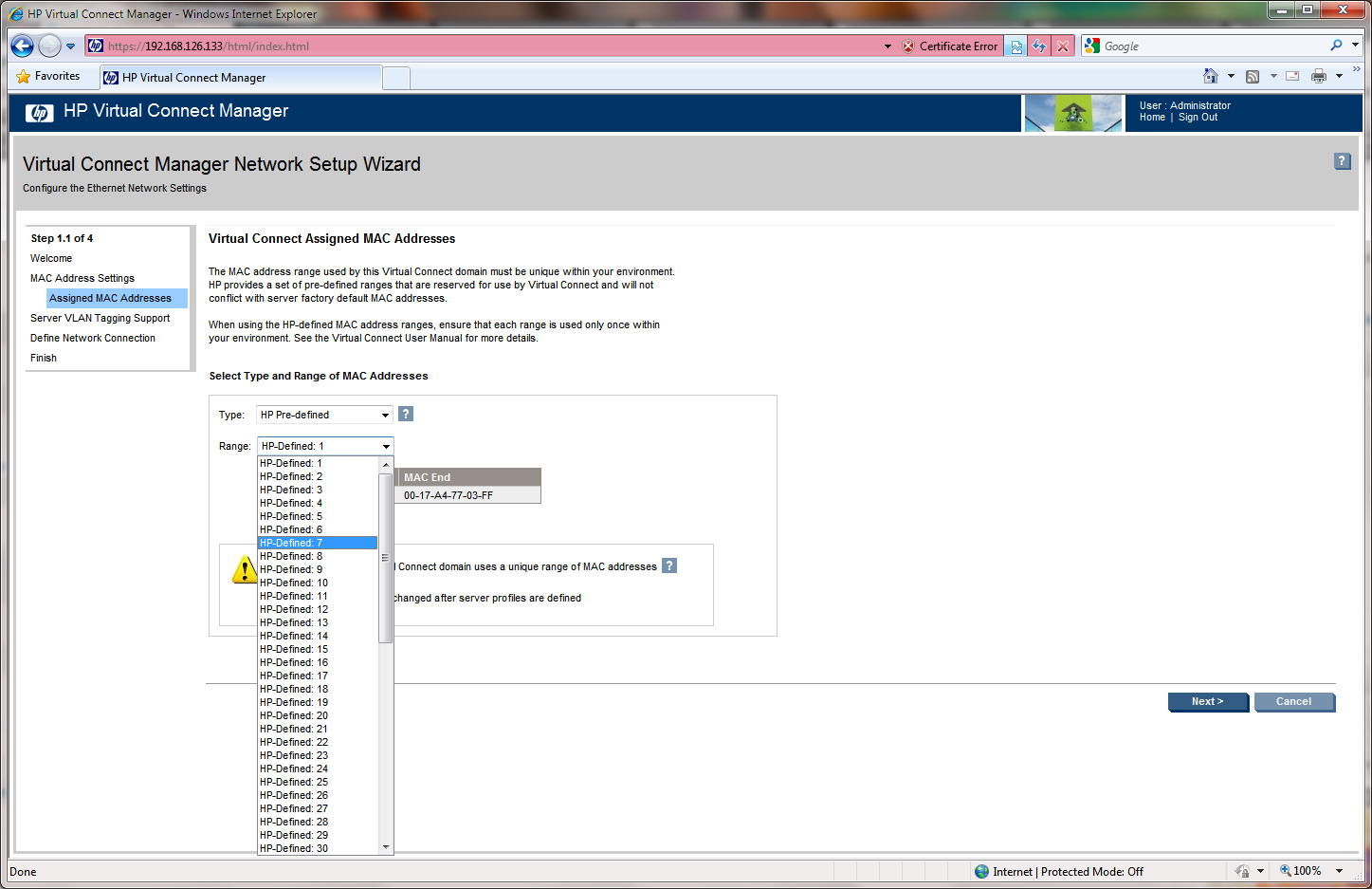
Once you have chosen the address range and click next the wizard will ask for confirmation before continue.
The next screen is Server VLAN Tagging Support. Here the wizard gives you two possible options:
- Tunnel VLAN Tags
- Map VLAN Tags
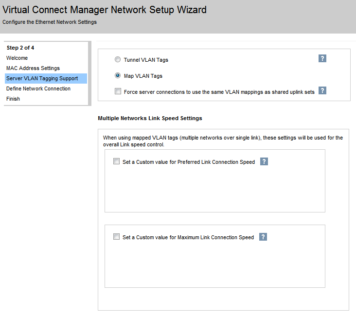
The first one, Tunnel VLAN Tags, supports only VLAN tagging on networks with dedicated uplinks where all VLAN tags passed through the VC Domain without modification and ports connected to networks using shared uplinks can only send and receive untagged frames.
On the other hand Map VLAN Tags allow you to add more than one network to an Ethernet server port and specify the VLAN mapping between server tags and VC-Enet networks. Also, the VLAN tunneling will be disabled for VC Ethernet networks with dedicated uplinks.
There is also a checkbox in the page to Force server connections to use the same VLAN mappings as shared uplink sets, if this option is enabled the server ports connected to multiple VC Ethernet networks are forced to use the same VLAN mappings as those used for the corresponding Shared Uplink Set and the network connections can only be selected from a single Shared Uplink Set. When this option is not checked server network connections can be selected from any VC network and the external VLAN ID mappings can be manually edited. In the example of the screenshots I decided to check it.
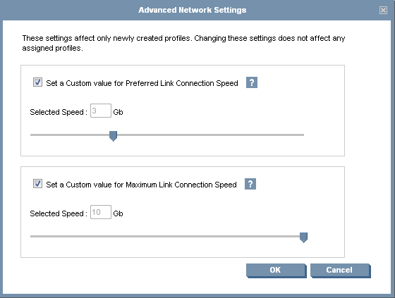
Below are another two optional settings for link speed control when using mapped VLAN tags. These settings are:
- Set a Custom value for Preferred Link Connection Speed. This value applies to server profiles with a Multiple Networks connection defined and the Port Speed Setting set to Preferred.
- Set a Custom value for Maximum Link Connection Speed. This value limits the maximum port speed for multi-network connections when a Custom port speed is specified.
In our example we’re not going to check neither of them . Click next to move into the Define Network Connection screen.
Choose the network type you want to define and click next. I choose Connection with uplink(s) dedicated to a single network.
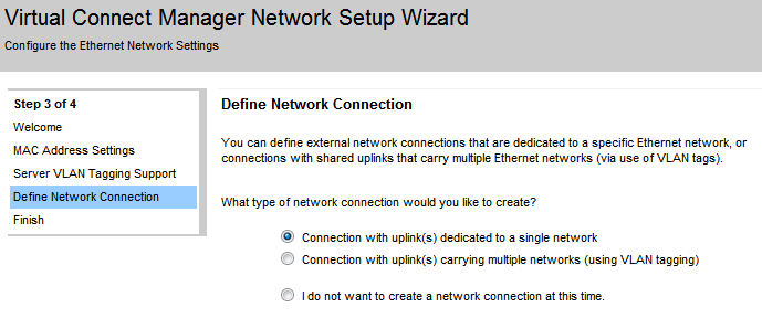
The Define Single Network window shows up. First define the network name (prod_net_01 in my example). There are three configurable values.
- Smart Link - With this option enabled Virtual Connect will drop the Ethernet link on every server connected to that network if the link to the external switches is lost.
- Private Network - This option is intended to provide extra network security by isolating all server ports from each other within the VC Domain. All packets will be sent through the VC Domain and out the uplinks ports so the communication between the severs will go through an external L3 router that will redirect the traffic back to the Domain.
- Enable VLAN Tunneling.

Click the Advanced button to configure Advanced Network Settings. Set the network link speeds that best suites your configuration.
Again from the Define Single Network page we are going to assign a port to our network. Click on Add Port and select an uplink port.
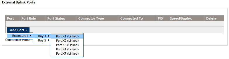
Set the Connection Mode to Auto if the ports are trunked and to *Failver* if not.
Click Apply and move onto the next screen. From this screen you can create as many additional networks as you need.

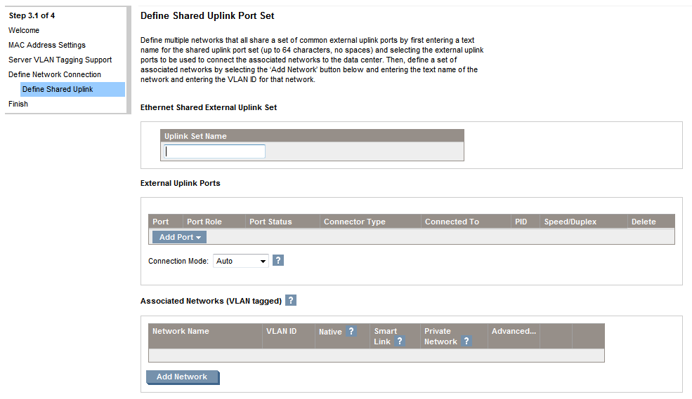
Now we are going to create a network using VLAN tagging. Click Next an move again into the Define Network Connection page, select Connection with uplink(s) carrying multiple networks (using VLAN tagging) and click Next. The Define Shared Uplink Port Set page will be displayed.
A shared uplink is the way Virtual Connect has to identify which uplinks carry multiple networks over the same cable. On shared uplinks the VLAN tags are added when packets leave the enclosure and added when leave. The external switch and the Virtual Connect Manager must be configured with the same VLAN tag ID for each network on the shared uplinks. The uplinks enables multiple ports to be added in order to support port aggregation and link failover, with a consistent set of VLAN tags. Virtual Connect has no restriction on which VLAN IDs can be used so the VLANs already used in the external infrastructure can be used here.
Since the VLAN tags are removed or added as soon as the packet enter or leave VC Ethernet Module shared uplink they have no relevance after the packet enter the enclosure. By identifying an associated network as the native VLAN will cause all untagged incoming packets to be placed onto this network, just one network can be designated as the native VLAN.
To finish the network creation assign a name (up to 64 characters with no spaces), add a port using the drop-down menu like in the single network process described above and add the networks you want to associate to the uplink. Finally click Apply.
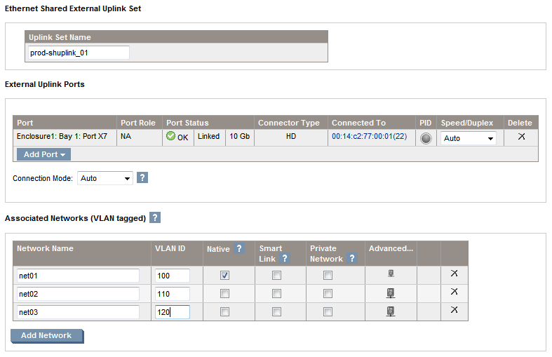
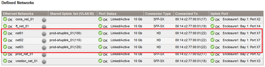
In the final screen you will see now the three networks associated to a Shared Uplink Set. You can check this also from the Virtual Connect Manager page in the Ethernet Networks area.
And we are done with the Network Setup, in the next post I will show the storage part. As always any feedback would be welcome.
Juanma.
Comments